Non-Planar Faces#
Description#
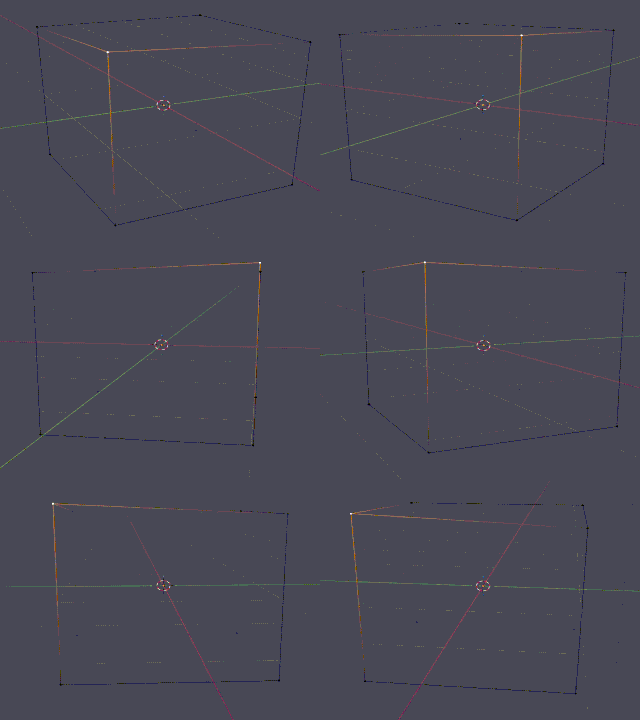
A non-planar face is a polygon whose vertices do not all lie in the same plane. Non-planar boundary faces can cause tetrahedral meshing to fail or can produce poor-quality boundary triangulation, increasing the risk of sliver, low-volume, or badly angled tetrahedra. Such faces should be planarized or explicitly triangulated before tetrahedral meshing.
Detection#
Detection Method: Perpendicular distance from best-fit plane
Tolerances:
Non-Planar Threshold:
1e-4m (0.1 mm)
Detection process:
Fit a best-fit plane to all vertices of the face (least-squares)
Calculate maximum perpendicular distance of any vertex from the plane
Calculate RMS (root mean square) distance
Note
Tolerances are distance-based (absolute). Large models have the same absolute tolerance, which may be more permissive relative to their size. Unlike zero area faces (which are inherently invalid), moderate non-planarity is often acceptable.
Auto-Repair#
Status: ❌ No automatic repair
Action: Detection and reporting only
Non-planar faces are detected and reported in the issue list but not automatically fixed. This allows users to:
Inspect which regions have planarity issues
Decide whether to accept the geometry as-is
Manually repair in CAD if needed
Why no auto-repair? There is no single “correct” repair for a non-planar face:
Project all vertices onto the plane (changes vertex positions)
Triangulate into smaller planar faces (increases face count)
Re-mesh the region (complex topology changes)
Manual Fix / Avoidance#
In 3D Modelling Tools (Before Export):
Check mesh quality: - Use CAD mesh checking tools - Look for high-aspect-ratio faces or skewed elements - Visualize face normals to spot inconsistencies